How To Test A 3 Phase Motor

Ever looked at a big, chunky motor – the kind that powers something serious, like a factory machine or a massive pump – and wondered, "How do they even know it's working right?" These aren't your average kitchen appliance motors, oh no. We're talking about the heavy hitters, the three-phase kind. And if you've ever been curious about what goes on under the hood, or more accurately, the junction box, you're in for a treat. Testing one of these bad boys isn't rocket science, but it is pretty darn cool, like being a detective for electricity.
So, why should you care about testing a three-phase motor? Well, imagine you're building a magnificent robot, or perhaps you've just inherited a vintage piece of machinery. You want to bring it back to life, right? Or maybe you're a budding electrician, or just someone who likes to tinker with things. Understanding how these motors work and how to check their health is like having a secret superpower in the world of mechanical and electrical stuff. It’s all about understanding the silent hum of power and making sure it's a happy, healthy hum.
Think of a three-phase motor like a perfectly choreographed dance. Instead of one dancer, you have three, and they all move in a specific sequence, creating a powerful, consistent rotation. This "dance" is thanks to three separate alternating current (AC) power lines, each slightly out of step with the others. It's this synchronized effort that gives three-phase motors their amazing ability to deliver smooth, powerful torque, making them ideal for demanding jobs. Pretty neat, huh?
Must Read
Now, when it comes to testing, we're essentially checking if this dance is being performed flawlessly. We want to make sure each dancer (or winding, as we call them in motor-speak) is doing its part and that they're all playing nicely together. It’s like checking the health of a finely tuned instrument before a big concert. You wouldn't just plug in a Stradivarius and hope for the best, would you? You'd give it a gentle tune-up.
The first thing you’ll likely want to do, even before touching any wires, is a good old-fashioned visual inspection. This is the "are you even plugged in?" stage of testing. Look for anything obvious that’s wrong. Are there any burnt wires? Is the casing cracked or damaged? Does it look like a squirrel decided to build a nest inside? Sometimes, the simplest things are the most telling. It’s the motor’s way of saying, "Hey, something's not quite right here, pal!"

Next up, let's talk about the multimeter. This little gadget is your best friend in the world of electrical testing. It’s like a Swiss Army knife for electricity, capable of measuring voltage, current, and resistance. For testing a three-phase motor, we'll be focusing on its resistance measuring capabilities. Think of resistance as the motor's "effort" to let electricity flow through its internal wires, called windings. If this effort is too high or too low, it’s a sign of trouble.
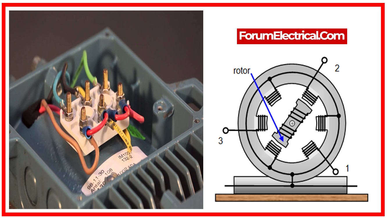
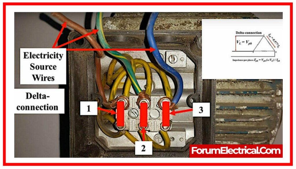
To test the windings, you'll need to find the motor's terminal box. This is usually a small, often metal, enclosure on the motor where all the wires connect. Inside, you'll typically find three main terminals, sometimes labeled T1, T2, and T3, or U, V, and W. These are the entry points for our three phases of power. You might also see other terminals, depending on the motor's configuration, but for a basic test, we're focused on these three.

The core of the winding test involves measuring the resistance between each pair of these main terminals. You'll set your multimeter to the resistance setting (usually denoted by the Greek letter Omega, $\Omega$). Then, carefully place your multimeter probes on two of the terminals, say T1 and T2. You should get a resistance reading. Then, move to T2 and T3, and then T3 and T1. What you're looking for is consistency. All three readings should be very close, if not identical. If one reading is significantly higher or lower than the others, it suggests a problem with one of the windings. It’s like noticing one of the dancers is a bit sluggish compared to the others – the rhythm is off!
What constitutes "close"? Well, for most common motors, the readings should be within a few ohms of each other. If you get a reading of infinity (meaning an open circuit, like a broken wire) on any pair, that’s a definite problem. If you get a reading of zero or very close to zero (meaning a short circuit, where the wires are touching when they shouldn't be), that's also a big red flag.
Another important test is checking for ground faults. Imagine the motor has an invisible shield protecting its internal workings. A ground fault is like a hole in that shield, where the electrical current can escape and flow to the motor's metal casing. This is dangerous! To test this, you'll measure the resistance between each of the main terminals (T1, T2, T3) and the motor's metal frame or casing. Again, you're looking for a reading of very high resistance, ideally infinity. If you get a low resistance reading here, it means there's a path for electricity to escape to ground, and the motor is not safe to operate.
So, what if you find a problem? Well, sometimes a loose connection can be the culprit, and a simple tightening might fix it. Other times, a winding might be damaged or burnt, and that might mean the motor needs to be replaced or sent for professional repair. It’s not always a DIY fix, and that’s okay! Knowing when to call in the cavalry is part of the smart tinkerer’s toolkit.
Beyond the basic resistance tests, more advanced diagnostics exist. For instance, you might hear about megger testing. A megger (or insulation tester) is like a super-powered multimeter that applies a much higher voltage to test the insulation’s integrity. It's a more thorough way to check for those sneaky ground faults and winding insulation breakdown. Think of it as giving the motor’s shield a really robust inspection.
And what about when the motor is actually running? This is where you might use your multimeter to check for the correct voltage at the terminals. If the voltage is too low or unbalanced between the phases, the motor won't perform optimally and could even be damaged. This is like making sure each dancer is getting enough energy to keep up with the music!
It’s also interesting to note that three-phase motors can be wired in different configurations, most commonly star (or wye) and delta. The internal connections within the terminal box will dictate which configuration is being used. Understanding this is key because it affects how you might test certain aspects and how the motor is powered. It's like knowing whether your dancers are performing a circle or a line formation – it changes the dynamics!
Ultimately, testing a three-phase motor is about understanding its electrical heart. It’s about listening to its silent signals and making sure it’s ready to do its job reliably and safely. It’s a little bit of detective work, a dash of electrical know-how, and a whole lot of satisfaction when you can confidently say, "Yep, this motor's good to go!" So, next time you see one of these powerful beasts, you'll have a better appreciation for what makes it tick, and maybe even feel a little curious about giving it a friendly check-up yourself.

